Refer to the exhibit.
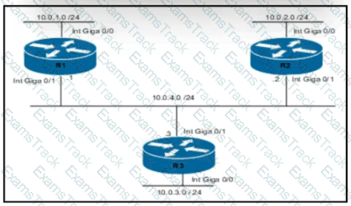
Routers R1 and R3 have the default configuration The router R2 priority is set to 99 Which commands on R3 configure it as the DR in the 10.0.4.0/24 network?
Refer to Exhibit.
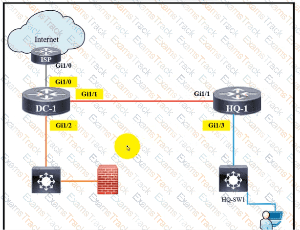
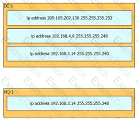
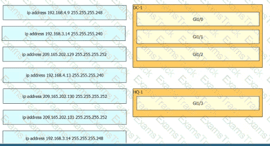
Rotor to the exhibit. The IP address configurations must be completed on the DC-1 and HQ-1 routers based on these requirements:
DC-1 Gi1/0 must be the last usable address on a /30
DC-1 Gi1/1 must be the first usable address on a /29
DC-1 Gi1/2 must be the last usable address on a /28
HQ-1 Gil/3 must be the last usable address on a /29
Drag and drop the commands from the left onto the destination interfaces on the right. Not all commands are used
Refer to the exhibit.

What is the next hop for traffic entering R1 with a destination of 10.1.2.126?
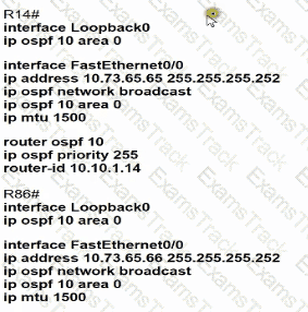
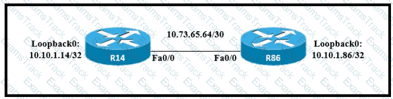
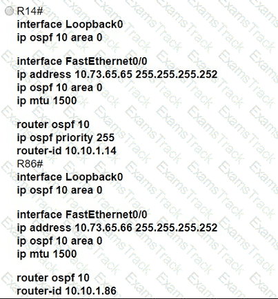
Refer to the exhibit.
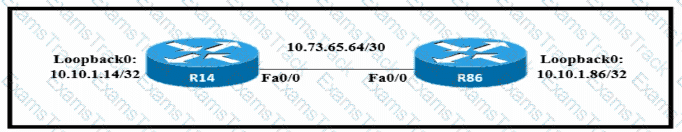
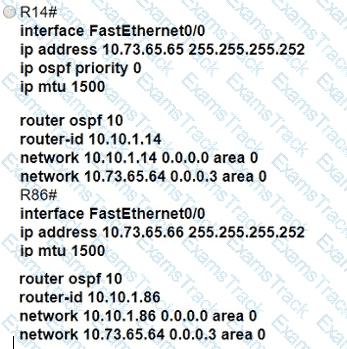
Which configuration allows routers R14 and R86 to form an OSPFv2 adjacency while acting as a central point for exchanging OSPF information between routers?
A)
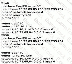
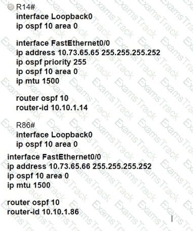
B)
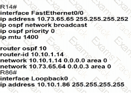
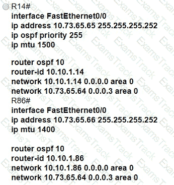
C)
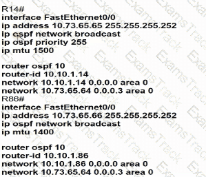
D)
An engineer configures interface Gi1/0 on the company PE router to connect to an ISP Neighbor Discovery is disabled
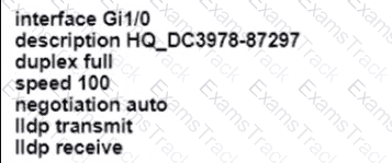
Which action is necessary to complete the configuration if the ISP uses third-party network devices?
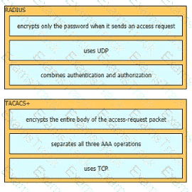
Drag and drop the functions of AAA supporting protocols from the left onto the protocols on the right.
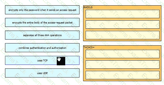
How does authentication differ from authorization?
Which field within the access-request packet is encrypted by RADIUS?
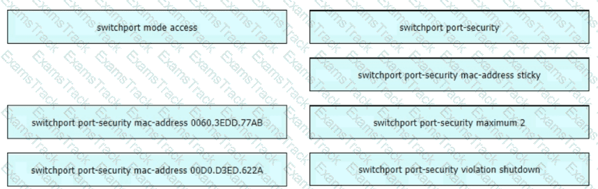
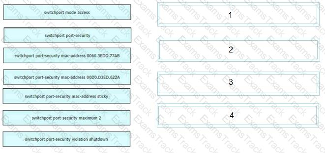
An engineer is tasked to configure a switch with port security to ensure devices that forward unicasts multicasts and broadcasts are unable to flood the port The port must be configured to permit only two random MAC addresses at a time Drag and drop the required configuration commands from the left onto the sequence on the right Not all commands are used.
Which action implements physical access control as part of the security program of an organization?
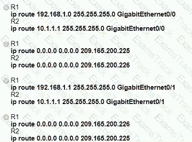
Refer to the exhibit.
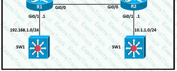
A network engineer is in the process of establishing IP connectivity between two sites. Routers R1 and R2 are partially configured with IP addressing. Both routers have the ability to access devices on their respective LANs. Which command set configures the IP connectivity between devices located on both LANs in each site?
Refer to the exhibit.
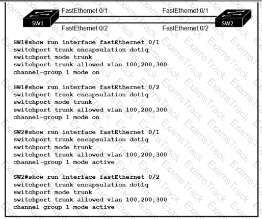
An engineer built a new Layer 2 LACP EtherChannel between SW1 and SW2 and executed these show commands to verify the work. Which additional task allows the two switches to establish an LACP port channel?
What are two benefits of using the PortFast feature? (Choose two )
A network engineer is replacing the switches that belong to a managed-services client with new Cisco Catalyst switches. The new switches will be configured for updated security standards, including replacing Telnet services with encrypted connections and doubling the modulus size from 1024. Which two commands must the engineer configure on the new switches? (Choose two.)
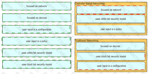
What is the function of " off-the-shelf " switches in a controller-based network?
Refer to the exhibit.
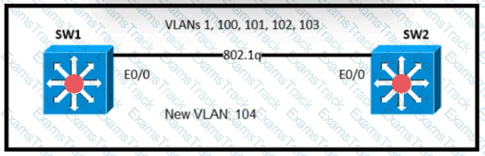
An engineer is asked to insert the new VLAN into the existing trunk without modifying anything previously configured Which command accomplishes this task?
OSPF must be configured between routers R1 and R2. Which OSPF configuration must be applied to router R1 to avoid a DR/BDR election?
Refer to the exhibit.
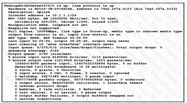
Traffic that is flowing over interface TenGigabitEthernet0/0 experiences slow transfer speeds. What is the reason for the issue?
Refer to the exhibit.
All interfaces are configured with duplex auto and ip ospf network broadcast. Which configuration allows routers R14 and R86 to form an OSPFv2 adjacency and act as a central point for exchanging OSPF information between routers?
What is the MAC address used with VRRP as a virtual address?
|
PDF + Testing Engine
|
|---|
|
$52.5 |
|
Testing Engine
|
|---|
|
$40.5 |
|
PDF (Q&A)
|
|---|
|
$34.5 |
Cisco Free Exams |
|---|
|
Copyright © 2026 Examstrack. All Rights Reserved

TESTED 06 Jul 2026