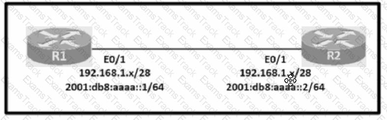
Configure IPv4 and IPv6 connectivity between two routers. For IPv4, use a /28 network from the 192.168.1.0/24 private range. For IPv6, use the first /64 subnet from the 2001:0db8:aaaa::/48 subnet.
1. Using Ethernet0/1 on routers R1 and R2, configure the next usable/28 from the 192.168.1.0/24 range. The network 192.168.1.0/28 is unavailable.
2. For the IPv4 /28 subnet, router R1 must be configured with the first usable host address.
3. For the IPv4 /28 subnet, router R2 must be configured with the last usable host address.
4. For the IPv6 /64 subnet, configure the routers with the IP addressing provided from the topology.
5. A ping must work between the routers on the IPv4 and IPv6 address ranges.
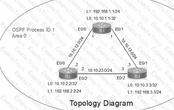
IP connectivity between the three routers is configured. OSPF adjacencies must be established.
1. Configure R1 and R2 Router IDs using the interface IP addresses from the link that is shared between them.
2. Configure the R2 links with a max value facing R1 and R3. R2 must become the DR. R1 and R3 links facing R2 must remain with the default OSPF configuration for DR election. Verify the configuration after clearing the OSPF process.
3. Using a host wildcard mask, configure all three routers to advertise their respective Loopback1 networks.
4. Configure the link between R1 and R3 to disable their ability to add other OSPF routers.
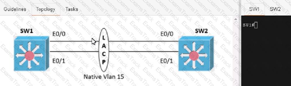
Physical connectivity is implemented between the two Layer 2 switches, and the network connectivity between them must be configured
1. Configure an LACP EtherChannel and number it as 1; configure it between switches SW1 and SVV2 using interfaces Ethernet0/0 and Ethernet0/1 on both sides. The LACP mode must match on both ends
2 Configure the EtherChannel as a trunk link.
3. Configure the trunk link with 802.1 q tags.
4. Configure the native VLAN of the EtherChannel as VLAN 15.
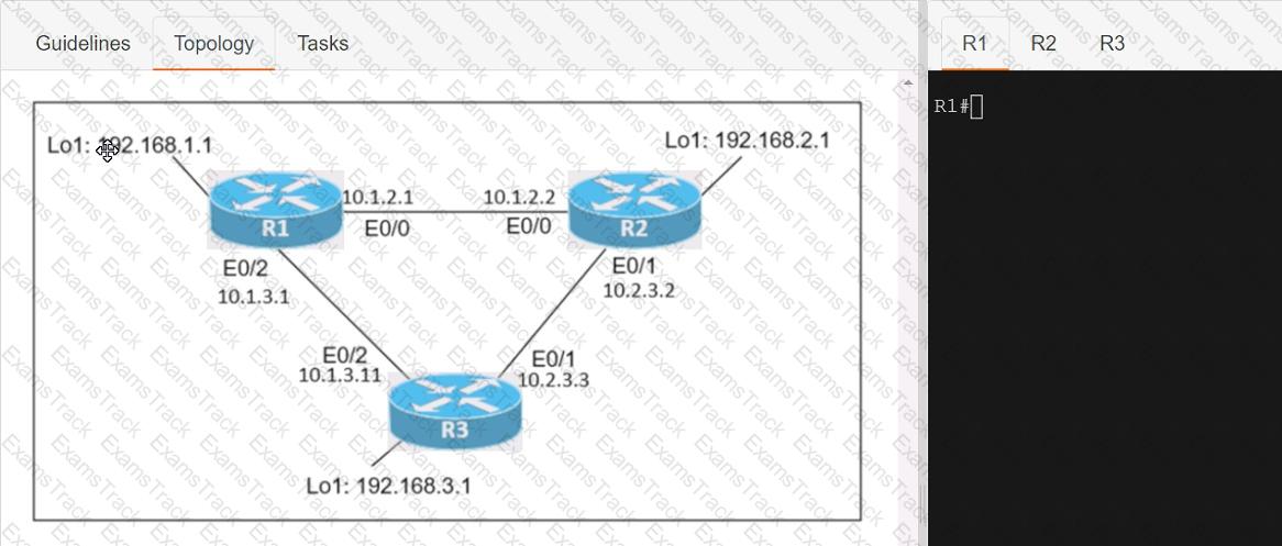

Connectivity between three routers has been established, and IP services must be configured jn the order presented to complete the implementation Tasks assigned include configuration of NAT, NTP, DHCP, and SSH services.
1. All traffic sent from R3 to the R1 Loopback address must be configured for NAT on R2. All source addresses must be translated from R3 to the IP address of Ethernet0/0 on R2, while using only a standard access list named NAT To verify, a ping must be successful to the R1 Loopback address sourced from R3. Do not use NVI NAT configuration.
2. Configure R1 as an NTP server and R2 as a client, not as a peer, using the IP address of the R1 Ethernet0/2 interface. Set the clock on the NTP server for midnight on January 1, 2019.
3. Configure R1 as a DHCP server for the network 10.1.3.0/24 in a pool named TEST. Using a single command, exclude addresses 1-10 from the range. Interface Ethernet0/2 on R3 must be issued the IP address of 10.1.3.11 via DHCP.
4. Configure SSH connectivity from R1 to R3, while excluding access via other remote connection protocols. Access for user root and password Cisco must be set on router R3 using RSA and 1024 bits. Verify connectivity using an SSH session from router R1 using a destination address of 10.1.3.11. Do NOT modify console access or line numbers to accomplish this task.
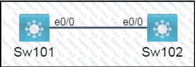
All physical cabling is in place. A company plans to deploy 32 new sites.
The sites will utilize both IPv4 and IPv6 networks.
1 . Subnet 172.25.0.0/16 to meet the subnet requirements and maximize
the number of hosts
Using the second subnet
• Assign the first usable IP address to e0/0 on Sw1O1
• Assign the last usable IP address to e0/0 on Sw102
2. Subnet to meet the subnet requirements and maximize
the number of hosts
c Using the second subnet
• Assign an IPv6 GUA using a unique 64-Bit interface identifier
on e0/0 on Sw101
• Assign an IPv6 GUA using a unique 64-Bit interface identifier
on eO/O on swi02
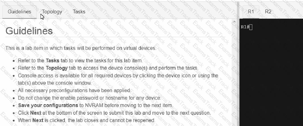
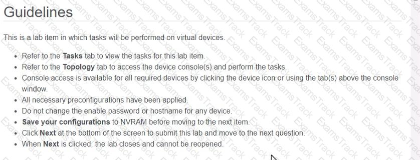
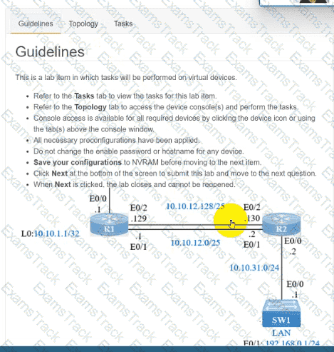
Guidelines
This is a lab item in which tasks will be performed on virtual devices.
• Refer to the Tasks tab to view the tasks for this lab item.
• Refer to the Topology tab to access the device console(s) and perform the tasks.
• Console access is available for all required devices by clicking the device icon or using
the tab(s) above the console window.
• All necessary preconfigurations have been applied.
• Do not change the enable password or hostname for any device.
• Save your configurations to NVRAM before moving to the next item.
• Click Next at the bottom of the screen to submit this lab and move to the next question.
• When Next is clicked, the lab closes and cannot be reopened.
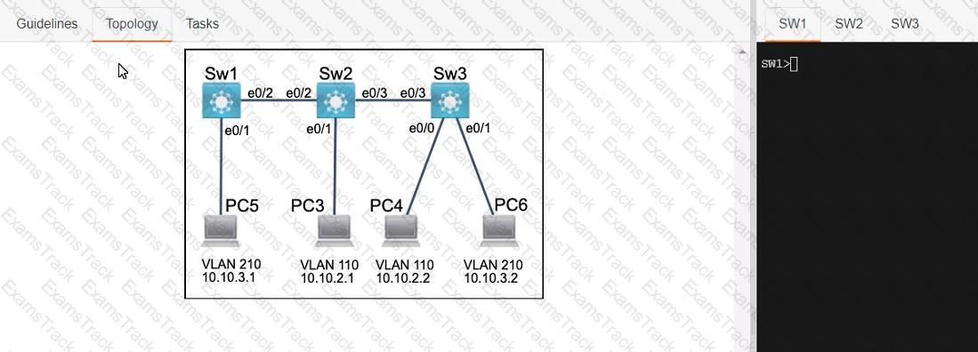
Three switches must be configured for Layer 2 connectivity. The company requires only the designated VLANs to be configured on their respective switches and permitted accross any links between switches for security purposes. Do not modify or delete VTP configurations.
The network needs two user-defined VLANs configured:
VLAN 110: MARKETING
VLAN 210: FINANCE
1. Configure the VLANs on the designated switches and assign them as access ports to the interfaces connected to the PCs.
2. Configure the e0/2 interfaces on Sw1 and Sw2 as 802.1q trunks with only the required VLANs permitted.
3. Configure the e0/3 interfaces on Sw2 and Sw3 as 802.1q trunks with only the required VLANs permitted.
Refer to the exhibit.
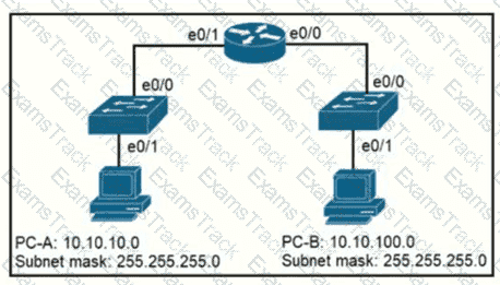
When PC-A sends traffic to PC-B, which network component is in charge of receiving the packet from PC-A verifying the IP addresses, and forwarding the packet to PC-B?
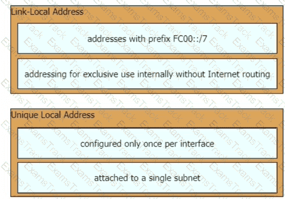
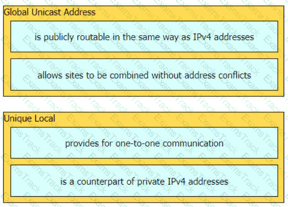
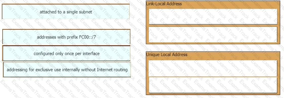
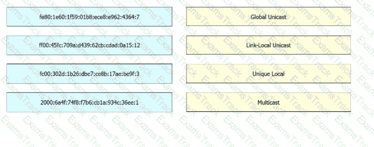
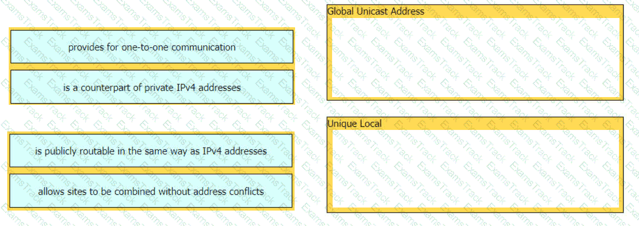
Drag and drop the IPv6 address type characteristics from the left to the right.
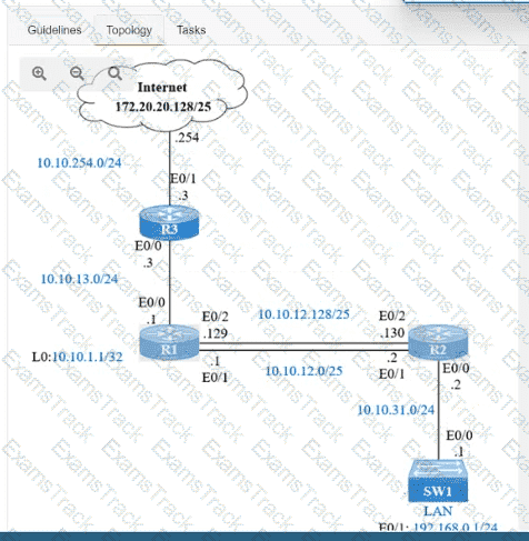
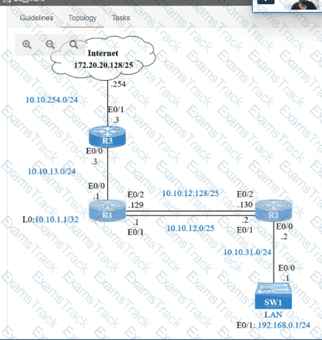
IP connectivity and OSPF are preconfigured on all devices where necessary. Do not make any changes to the IP addressing or OSPF. The company policy uses connected interfaces and next hops when configuring static routes except for load balancing or redundancy without floating static. Connectivity must be established between subnet 172.20.20.128/25 on the Internet and the LAN at 192.168.0.0/24 connected to SW1:
1. Configure reachability to the switch SW1 LAN subnet in router R2.
2. Configure default reachability to the Internet subnet in router R1.
3. Configure a single static route in router R2 to reach to the Internet subnet considering both redundant links between routers R1 and R2. A default route is NOT allowed in router R2.
4. Configure a static route in router R1 toward the switch SW1 LAN subnet where the primary link must be through Ethernet0/1. and the backup link must be through Ethernet0/2 using a floating route. Use the minimal administrative distance value when required.
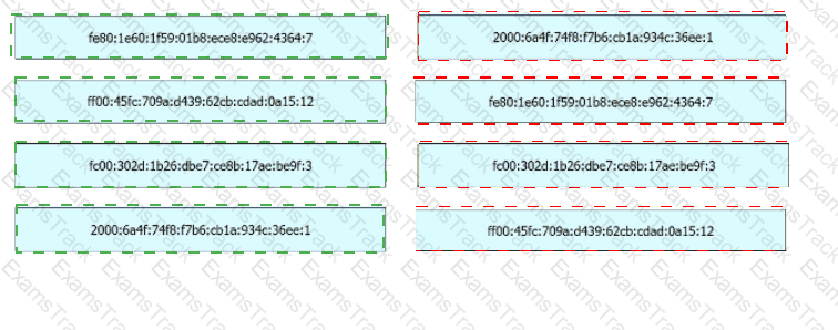
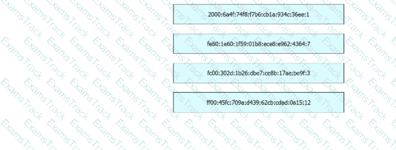
Drag and drop the IPv6 addresss froin the left onto the type on the right.
A network architect is deciding whether to implement Cisco autonomous access points or lightweight access points. Which fact about firmware updates must the architect consider? Unlike lightweight access points, which require
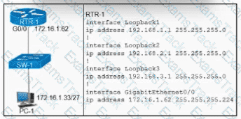
Refer to the exhibit. Which configuration for RTR-1 denies SSH access from PC-1 to any RTR-1 interface and allows all other traffic?
How are API keys used to enforce rate limiting?
How does network automation help reduce network downtime?
Aswitch receives a frame with the destination MAC addresss 3C:5D: 7E:9F: 1A:2B.
Switch# show ethernet-frame-and-mac-addresss-table
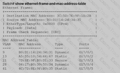
How does the switch handle the frame?
Refer to the exhibit.
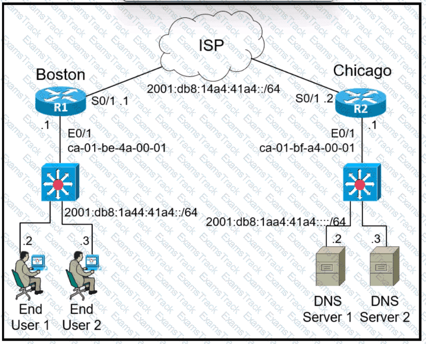
Refer to the exhibit. The IPv6 address for the LAN segment on router R1 must be configured using the EUI-64 format. When configured which ipv6 address is produced by the router?
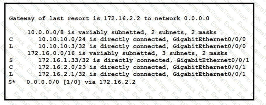
Refer to the exhibit. A packet sourced from 10.10.10.1 is destined for 172.16.3.254. What is the subnet mask of the destination route?
What is a characteristic of a Layer 2 switch?
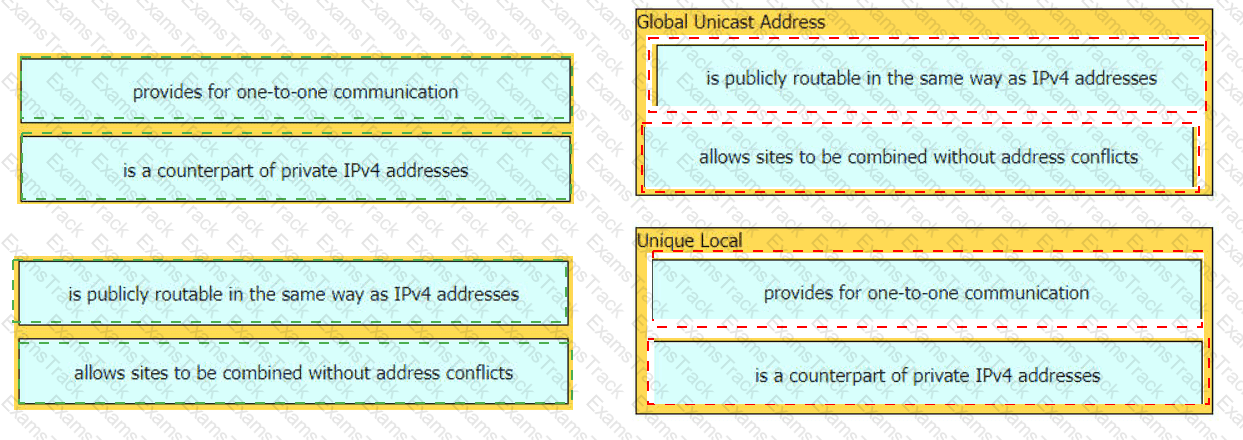
Drag and drop the characteristic from the left onto the IPv6 address type on the right.
Which event has occurred if a router sends a notice level message to a syslog server?
|
PDF + Testing Engine
|
|---|
|
$52.5 |
|
Testing Engine
|
|---|
|
$40.5 |
|
PDF (Q&A)
|
|---|
|
$34.5 |
Cisco Free Exams |
|---|

|
Copyright © 2026 Examstrack. All Rights Reserved

TESTED 07 Jul 2026